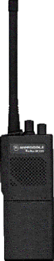

GP300
Radio Programming,
8 to 16 channel expansion.
RIB-IVG (Radio Programming Interface)
Introduction.
The Motorola GP300 can be re-programmed quite easily to allow use on our Amateur Radio bands. The radio is made in both a VHF and UHF versions, and makes an excellent 2mtr or 70cms portable radio.
Most of the radio's I have worked on have originally been 8 channel units. These can be modified to operate on 16 channels quite easily.
The programming interface can be made for a low cost. All it consists of is a RS232 to TTL level converter, that connects between the serial port of your PC and the radio.
![]()
Amateur Radio Conversion.
The radio requires the Motorola Software which can be found if you ask around or search for it on the FTP sites on the Internet. If you can't find it then try your local Motorola dealer who should be able to help at a small cost.
You also have to make an interface, or purchase one.
To program the radio onto the Amateur band, you can find some versions of software that have been hacked into allowing frequencies to be entered to bring the radio into the amateur bands which normally are just bellow the original working frequency. However this depends on your version of software, if it's a un-hacked version then you have to press the <SHIFT> key down when entering the frequency. You must release the <SHIFT> key when entering the decimal point. For example to program 433.500MHz you will enter the following: $ŁŁ.%)) on a English layout keyboard. (This is 433.500 with the <SHIFT> held down. Fill all of the 0's in the frequency field. This example is the same for both the VHF and UHF GP300's.
![]()
16 Channel conversion. (for 8 channel radio's only)
To program the radio for 16 channels you need to first of all, pull the channel selector knob off the radio. On the underside of the channel selector knob you will see a small black "Stop". Cut this off with a sharp knife and replace the knob. You will now find the radio then switches 16 positions instead of the original 8 channels.
To program the radio for 16 channels all you need to do is edit a file called GP300.MDF. You do this with the help of a Hex editor such as Hex Workshop This can be found and downloaded on http://www.bpsoft.com
The file you need to modify is called GP300.MDF and can be found in the main directory of the Motorola software. Keep a backup of your original GP300.MDF file, just in case you make a mistake.
I have made a small video that shows the Hex Workshop screen during the modification. This should help you understand the procedure of editing the file which when complete will give you 16 channels. Click below to download.
gp300mdf.zip (364Kb)
Procedure
Get a copy of Hex Workshop. ( http://www.bpsoft.com )
Start the Hex Workshop program and open the file GP300.MDF to begin editing.
Go to "Tools", and the "Generate Checksum".
Make sure "Entire Document" and also "Decimal" are ticked. Then press "Generate".
Look in the "Checksum-16" box, in my version of software for example, this results in a checksum of 53454 (yours may be a different number depending on the version of Motorola software)
Write this number down, as you need it later.
Press "Cancel" to return to the main window and your next step.
Go to "Edit" and then "Find". A pop-up window appears.
You need to enter the model number of your radio. For e.g. P93YPC00D2AB.
When you enter the model number leave off the last two letters(AB on my radio).Make sure "ASCII" is ticked.
When you press "Find Next", you will see your model number highlighted.
If you count 8 numbers after the highlighted section, you should see the number "08" as long your radio is originally a 8 channel set.
Edit the "08" to "10" (note 10 in Hex is equal to 16 in decimal).
You now need to edit the start of the program, to allow the software to run.
In the first few lines look for a Hex number that you can easily take away 8 from.
In my software at address 00000040 you will see the number "78" on the right.
Edit this to be "70".
Now you must do a final checksum and make sure it equals the original value.
If this is the same, then replace you original file with the modified file.
Try to reprogram your radio with the extra 8 channels to give you 16 channels.
![]()
![]()
RIB-IVG (Programming Interface MkII) by G1IVG.
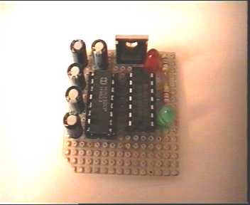
(with special thanks to Roberto EB4EQA for supplying the drawings below).
WARNING:
In order to build the interface described below, you will at least require some basic electronics experience. If you don't understand, how the described circuitry works, it's best not to build it. Although the described procedure is relatively simple, you could cause serious problems to both your PC and your Motorola radio. So please build the interface and use it at your own risk.
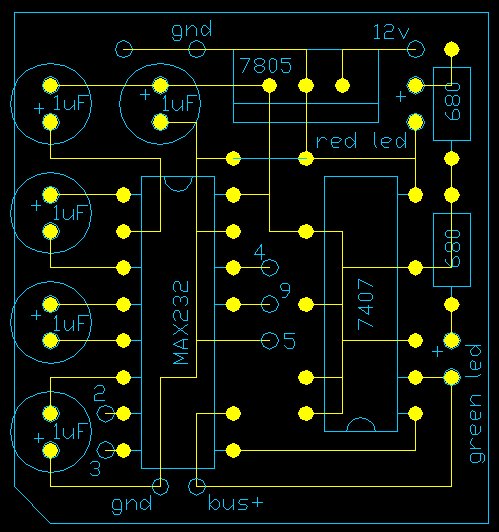
Pay attention to the polarity of the capacitors these are marked
with a + in the diagram next to each capacitor. You will find that in some cases the
capacitors appear to be the wrong way around, however this is not the case, as they must
be configured this way to generate the correct voltages within the MAX232.
Interface Parts List.
Item Qty Description
Component Side View
![]()
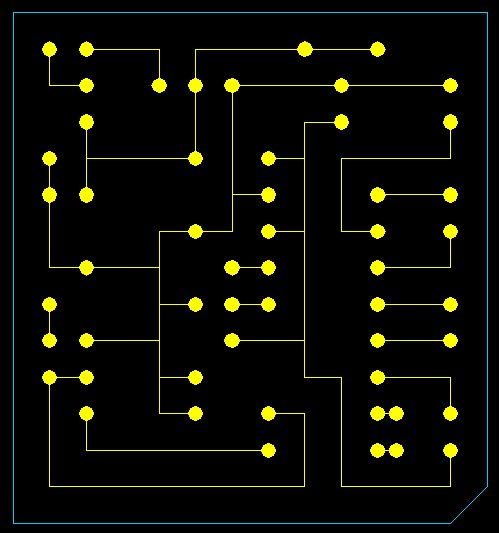
Track Side View
![]()
Click here to download a zip file that contains
an AutoCAD 14 file
of the images above.
PC Connection.
In the interface drawing above you will see the numbers 2,3,4,5 & 9. These numbers represent the 9pin serial port found on most PC's today. If you only have a 25pin serial port then see below for the pin-out translation.
9 pin to 25 pin conversion information.
9 pin 25 pin
2---------------------------3
3---------------------------2
4---------------------------20
5---------------------------7
9---------------------------22
Radio Connection (GP300).
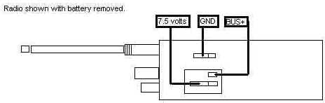
To connect to your GP300, all you have to do is temporarily connect your interface to the GND and BUS+ on the back of the radio. these connections are visible when the battery is removed.
You will also need a external 7.5vdc supply to power the radio when you are programming it. This is connected between the 7.5 volt and GND connection on the radio.
Notes:
If you have problems getting this interface to work on your GP300, then try replacing the two 680 ohm resistors that feed the LED's. If you use 4.7k ohm it should work OK. I found that when using version R01.00.00 software I have no problems with the 680 ohm resistors, but for some reason when I ran the newer software (R08.02.00) I had problems reading the codeplug etc. All I have done is replaced the 680 ohm with 4.7k ohm and it works fine now with both versions of software. You will have to experiment a little and let me know what resistors work for you.
Simon VK4TSC encountered a problem where the GP300 being programmed/read will fail to pass data to/from the computer with an Error #2 (Serial Bus Error). After checking the BUS+ line with a CRO it was found that the GP300 could not properly switch the data bus, this being caused by the led/resistor combination on the data bus drawing a little more current than the radio could supply. By changing the series resistor to 1K ohm instead of 680 ohm the problem was overcome
The better solution maybe to use a spare gate from the 7407 to drive the led separately. Disconnect led cathode and link it to pin 4 of 7407, isolate pin 3 of 7407 from 5V and link it to pin 2 of same chip. The original 680 ohm series resistor can be left as is. BUS+ is now isolated from the data led.
The Interface design above has been tested on the following radio's:
GM300 (Connect to the Mic socket on the front panel of the GM300)
GM350 (Connect to the Mic socket on the front panel of the GM350)
GP300 (See this page for info etc.)
Maxtrac 840 - 800 MHz Truncking Radio (Try http://www.batlabs.com for connections).
Maxtrac 300, VHF 16 ch.
(sh_gp300.zip 395KB)
![]()
Sandy Ganz's RIB Card PCB.
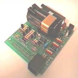
You can buy the RIB Card PCB direct from Sany Ganz in the form of a bare PCB. It cost me $20 plus $5 Overseas shipping. For further detailed information you can e-mail Sandy on the following address : motradio@pacbell.net All you need to do is purchase the components locally. Sandy also includes a parts list and information on a supplier for the components if you can't find them locally.
73 de Colin in Barcelona Spain.
![]()