
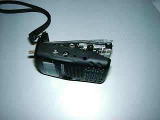
TH-F7E
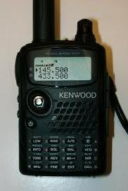
Extended TX Mods by G1IVG.
![]()
Notes:
This modification will reset your radio and therefore clear all pre-programmed memories etc.
If you have never removed surface mount devices before, then experiment on some old PCB's first, before destroying or making a mess of your new radio.
Make sure you use a low wattage soldering iron and tweezers to lift the components from the PCB.
If you decide to do this modification, you do entirely at your own risk.
![]()
The modification.
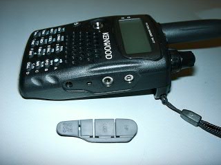
1. Remove the battery from the radio.
2. Remove the grey rubber protective cover from the right hand side of the radio.
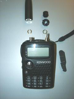
3. Remove the black plastic volume and frequency change knobs by gently pulling them vertically.
4. Remove the locking nut from the SMA aerial connector.
5. Remove the locking nut from the frequency change encoder / volume control shaft.
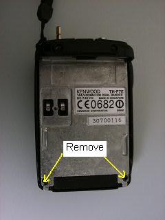
6. With the battery removed, look at the rear of the radio and remove the two screws at the bottom.
7. To open your radio's case. It's best to gently open the radio from the bottom until you have a gap of about 10mm. Then hold the front panel in the palm of your left hand and gently slide the main body of the radio downwards with your right hand, until the aerial and frequency change encoder shaft are clear of the holes in the top panel of the radio. Take care not to open the radio to fast, because the internal speaker wires are very short.
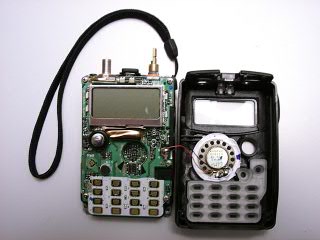
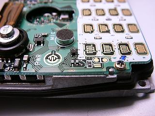
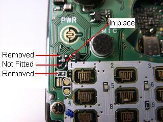
8. With the radio opened up like a book, look at the left hand side of the PCB just to the left of the PCB mounted microphone. You should see two diodes and also a open pad just below were another diode could be fitted.
These photo's shows radio before modification.
9. Remove only the top diode. There still should be a diode in the middle position and the bottom position should be left empty as original.
10. Finally look just below the lower open pad (3rd position) you should see a resistor to the left of the key pad number "1". This also must be removed to complete the modification.
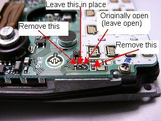
This photo shows radio after modification.
Reassemble the radio taking care not to trap the speaker wires and also check that the small joystick and keypad membrane seats correctly.
OK That's it.........................
![]()
The TH-F7E will now Transmit and Receive on the "A" band from:
137MHz to 174MHz FM.
410MHz to 470MHz FM.
WARNING.
Always use a tuned aerial for the frequency you intend to transmit on, as the original supplied aerial is only designed for use on our amateur 2m and 70cms bands.
If your aerial is not tuned for the frequency you wish to transmit on, damage to the PA in the radio can be caused if you transmit on high or even low power.............................You have been warned!!!!
Download Kenwood TH-F6/F7 Memory Control Software.
Download TH-F7 Sales brochure in PDF format.
Download the TH-F7e Instruction Manual in PDF format.
Download the TH-F7e Service Manual in PDF format.
![]()
![]()
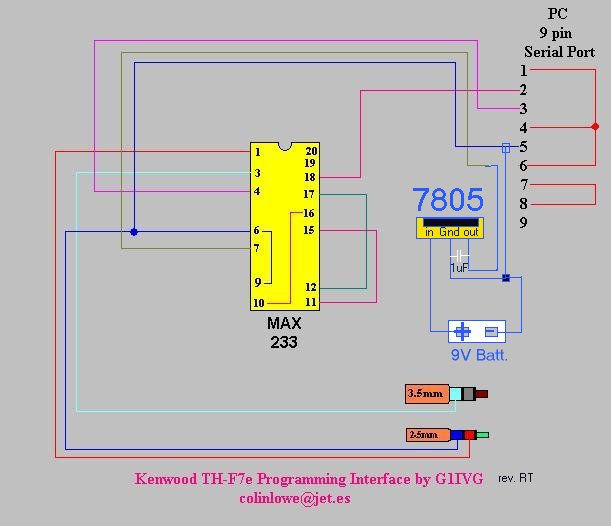
External PSU Version
If your PC struggles to supply the correct power required to drive the Max233 correctly, then try this simple mod below, to allow a external power supply such as a PP3 9v battery to be used, rather than dragging the power from your serial port.
Many thanks to RV for supplying the mod below.
![]()
My Visual Basic 6
Kenwood TH-F7e Control Program
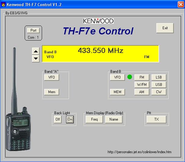
Download
Visual Basic Source Code for my TH-F7 Control V1.2 Program (36KB)
![]()
Other TH-F7 Links.
![]()