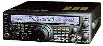
 FT847
FT847FT847
![]()
Note:
If you only wish to extend the RX and not the TX of the radio have a look at the resistor configuration at position number J4 in your radio (This is shown open in the photo below). if J4 it's fitted remove it. This will open the RX to allow the radio to receive outside the normal amateur bands. If you have a resistor or solder link in the position of J4, then your radio should be locked to RX only within the amateur bands on VHF and UHF.
The configuration of the resistors can done by simply replacing a resistor by soldering a blob of solder to bridge the gap in place of were a resistor should be.
If your not sure in any way about the mods, don't be afraid to ask. I will try to help you the best I can.
![]()
General Coverage TX Mods by G1IVG.
(Ideal for 40m expansion)
Procedure.
Disconnect all cables and connectors from your radio.
Remove the carry handle by taking out the two screws at each end of the handle.
Remove the other two screws on the opposite side of the radio.
Remove the two screws from the rear of the radio, that hold the top and bottom covers.
Remove the remaining two screws from the bottom cover near the front panel.
Now you can remove the bottom cover from the radio.
Place the radio on a clean surface with the top of the radio facing down.
Place the front panel towards you.
Now you should be able to see the Lithium battery to the top left hand side of the PCB.
Look closely and you will see 6 small surface mount resistors just below the battery and to the left.
They are labelled on the PCB as 1,2,3,4,5 & 6 (See photo below).
You need to configure the resistors as in the photo below.
After re-configuring the resistors double check your work and then replace all covers.
Finally you need to make a note of any memory channels you have programmed including offsets etc. As the CPU needs resetting to acknowledge the new configuration.
To reset the radio's CPU make sure the radio is OFF, then press and hold the <FAST> and <LOCK> button's and turn the radio ON. Remember all the contents of the memory channels will be reset and lost.
Also the Automatic Repeater Shift (ARS) will be lost. But all you need to do is, to reprogram the offset from the Menu option No:16 (10mtrs) Menu No:17 (6mtrs) Menu No:18 (2mtrs) and Menu No:19 (70cms)
NOTE:
The photo below shows the radio "AFTER" the modification.

Notes from the photo above:
The photo shows the radio "AFTER" the modification.
"In Place" means that a resistor must be fitted in this location.
"Solder Link" means that you must solder a bridge across the pad no:3, if a resistor is not fitted originally.
"Out" means, remove any resistor from this location.
The coverage of the radio
after the modification.
Receiver (the same as before the modification)
Band Min RX freq. Max RX freq.
H.F. 100KHz 37MHz
VHF (A) 37MHz 76MHz
VHF (B) 108MHz 174MHz
UHF 410MHz 512MHz
Transmitter
Band Min TX freq. Max TX freq.
H.F. 1.8MHz 37MHz
VHF (A) 37MHz 76MHz
VHF (B) 137MHz 174MHz
UHF 410MHz 460MHz
If you decide to carryout the same modification on your FT847, then you do so at your own risk.
This TX modification verified to work on the following serial numbers:
Note: "XXX" replaces the last three digits of the serial number for privacy reasons.
8C020XXX 8F040XXX 8G051XXX
8G060XXX 8G070XXX 8H080XXX
8H090XXX 8I100XXX 8J120XXX
8K130XXX 8K150XXX 8K151XXX
8L160XXX 8N170XXX 9E200XXX 9I240XXX
9I250XXX 0D280XXX OE310XXx
OI410XXX OM450XXX 1G490XXX
5E97XXXX 3F750XXX
Configuration of Chip Resistors.
As far as I know the information is correct, however proceed at your own risk.
TX Frequency Range |
RX Frequency Range |
Jumpers |
Remarks |
|||||||||||
HF |
VHF |
UHF |
HF |
VHF(M) |
VHF |
UHF |
1 |
2 |
3 |
4 |
5 |
6 |
FM CH Step |
RPT Shift |
1 |
144-146 |
430-450 |
0.1-30 50-54 |
144-146 |
430-450 |
X |
X |
X |
X |
5/20kHz |
0.6/5 MHz |
|||
1 |
144-148 |
430-450 |
0.1-37 37-76 |
108-174 |
420-512 |
X |
X |
X |
5/20kHz |
0.6/5 MHz |
||||
2 |
140-154 |
420-450 |
0.1-37 37-76 |
108-174 |
420-512 |
X |
X |
5/20kHz |
0.6/5 MHz |
|||||
3 |
144-146 |
430-440 |
0.1-30 50-54 |
144-146 |
430-440 |
X |
X |
X |
X |
12.5/25kHz |
0.6/7.5 MHz |
|||
3 |
144-146 |
430-440 |
0.1-37 37-76 |
108-174 |
420-512 |
X |
X |
X |
12.5/25kHz |
0.6/7.5 MHz |
||||
2 |
140-154 |
420-450 |
0.1-37 37-76 |
108-174 |
420-512 |
X |
X |
12.5/25kHz |
0.6/7.5 MHz |
|||||
4 |
144-146 |
430-440 |
0.1-30 50-54 |
70.00-70.50 |
144-146 |
430-440 |
X |
X |
X |
X |
X |
12.5/25kHz |
0.6/1.6 MHz |
|
4 |
144-146 |
430-440 |
0.1-37 37-76 |
108-174 |
420-512 |
X |
X |
X |
X |
12.5/25kHz |
0.6/1.6 MHz |
|||
5 |
140-154 |
420-450 |
0.1-37 37-76 |
108-174 |
420-512 |
X |
X |
X |
12.5/25kHz |
0.6/1.6 MHz |
||||
6 |
144-146 |
432-438 |
0.1-30 50-54 |
144-148 |
432-438 |
X |
X |
X |
X |
12.5/25kHz |
0.6/1.6 MHz |
|||
6 |
144-146 |
432-438 |
0.1-37 37-76 |
108-174 |
420-512 |
X |
X |
X |
12.5/25kHz |
0.6/1.6 MHz |
||||
7 |
144-148 |
430-450 |
0.1-30 50-54 |
144-148 |
430-450 |
X |
X |
X |
X |
X |
5/25kHz |
0.6/5 MHz |
||
7 |
144-148 |
430-450 |
0.1-37 37-76 |
108-174 |
420-512 |
X |
X |
X |
X |
5/25kHz |
0.6/5 MHz |
|||
8 |
144-146 |
430-440 |
0.1-30 50-54 |
144-146 |
430-440 |
X |
X |
X |
X |
X |
12.5/25kHz |
0.6/1.6 MHz |
||
8 |
144-146 |
430-440 |
0.1-37 37-76 |
108-174 |
420-512 |
X |
X |
X |
X |
12.5/25kHz |
0.6/1.6 MHz |
|||
2 |
140-154 |
420-450 |
0.1-37 37-76 |
108-174 |
420-512 |
X |
X |
X |
12.5/25kHz |
0.6/1.6 MHz |
||||
For HF, 6mtrs and 4mtrs range see table below.
160m |
80m |
40m |
30m |
20m |
17m |
15m |
12m |
10m |
6m |
4m |
|
1 |
1.800-2.000 |
3.500-4.000 |
7.000-7.300 |
10.100-10.150 |
14.000-14.350 |
18.068-18.168 |
21.000-21.450 |
24.890-24.990 |
28.000-29.700 |
50.000-54.000 |
|
2 |
1.800-2.000 |
3.500-4.000 |
7.000-7.500 |
10.000-10.500 |
14.000-14.500 |
18.000-18.500 |
21.000-21.500 |
24.500-25.000 |
28.000-30.000 |
50.000-54.000 |
|
3 |
1.815-1.890 |
3.500-3.800 |
7.000-7.100 |
10.100-10.150 |
14.000-14.350 |
18.068-18.168 |
21.000-21.450 |
24.890-24.990 |
28.000-29.700 |
50.080-50.400 |
|
4 |
1.810-2.000 |
3.500-3.800 |
7.000-7.100 |
10.100-10.150 |
14.000-14.350 |
18.068-18.168 |
21.000-21.450 |
24.890-24.990 |
28.000-29.700 |
50.000-52.000 |
70.000-70.500 |
5 |
1.800-2.000 |
3.500-4.000 |
7.000-7.500 |
10.000-10.500 |
14.000-14.500 |
18.000-18.500 |
21.000-21.500 |
24.500-25.000 |
28.000-30.000 |
50.000-52.000 |
70.000-70.500 |
6 |
1.820-1.890 |
3.500-3.800 |
7.000-7.100 |
10.100-10.150 |
14.000-14.350 |
18.068-18.168 |
21.000-21.450 |
24.890-24.990 |
28.000-29.700 |
50.000-52.000 |
|
7 |
1.800-2.000 |
3.500-4.000 |
7.000-7.500 |
10.000-10.500 |
14.000-14.500 |
18.000-18.500 |
21.000-21.500 |
24.500-25.000 |
28.000-30.000 |
50.000-52.000 |
|
8 |
1.810-1.850 |
3.500-3.800 |
7.000-7.100 |
10.100-10.150 |
14.000-14.350 |
18.068-18.168 |
21.000-21.450 |
24.890-24.990 |
28.000-29.700 |
50.200-51.200 |
![]()
Comment from KF9L
If you have a FT847 with serial number "OG340XXX" the factory settings of:
J1 = IN , J2 = OUT, J3 = OUT, J4 = OUT, J5 = IN and J6 = IN
Then to open the radio change for the following configuration
J1 = IN , J2=IN,J3=IN,J4=OUT,J5 = IN and J6 = IN
![]()
Download FT-847 Operating Manual (8.28 MB)
Download Yaesu FT847 Circuit diagram (3.39MB)
Download SSTV Interface diagram (64KB)
Download Kantronics KPC9612 Interface diagram (16KB)
FT847 Links
![]()
Peter, DH1NGP FT847 Supercontrol software
Yaesu FT847 Product Information.
Jeff, N30YQ's CAT control information and repeater hook-up